-torus.gif)
$\Delta V_{ab} = R\,I_{ab}$.
Note that $\displaystyle{\Delta V_{ba}= -\Delta V_{ab}}$ and $I_{ba} = -I_{ab}$.
The voltage differences and currents in a circuit must satisfy Kirchhoff's Laws
Elementary loops (meshes).
A mesh in a circuit is a loop that contains no smaller loops.
One way to organize the solution of the network
is in terms of mesh currents, the clockwise (say)
currents around the boundary of each mesh. The current in a segment
will be the algebraic sum of the currents from the two meshes
it belongs to (one if the segment is on the outside). This
gives a collection of unknowns $i_1, \dots, i_M$ where $M$ is
the number of meshes.
Applying KVL to each of the meshes gives a set of
$M$ equations which can be solved for $i_1, \dots, i_M$, thus
yielding the currents in all the segments and the solution of
the circuit.
 An example, adapted from Wikipedia, should show how the procedure
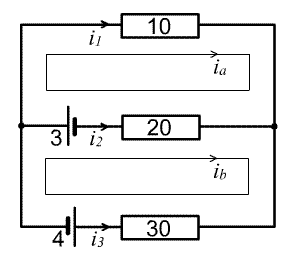
works. This circuit has voltage sources of
3 and 4 Volts and resistors of 10, 20 and 30
Ohms linked as in the diagram. Applying KVL to the top mesh, we add the voltage
increments
as we go around the boundary of the mesh, starting at the node
on the left: $-10 i_a - 20 (i_a-i_b) + 3 =0$; similarly the bottom mesh
yields $-3 -20 (i_b-i_a) -30 i_b -4 = 0$. Hence the system of linear
equations:
$$-30i_a+20i_b = -3$$
$$20i_a-50i_b=7,$$
which give $i_a=1/110\, \mbox{A},\,\, i_b=-15/110\, \mbox{A}$ and so
An example, adapted from Wikipedia, should show how the procedure
works. This circuit has voltage sources of
3 and 4 Volts and resistors of 10, 20 and 30
Ohms linked as in the diagram. Applying KVL to the top mesh, we add the voltage
increments
as we go around the boundary of the mesh, starting at the node
on the left: $-10 i_a - 20 (i_a-i_b) + 3 =0$; similarly the bottom mesh
yields $-3 -20 (i_b-i_a) -30 i_b -4 = 0$. Hence the system of linear
equations:
$$-30i_a+20i_b = -3$$
$$20i_a-50i_b=7,$$
which give $i_a=1/110\, \mbox{A},\,\, i_b=-15/110\, \mbox{A}$ and so(The Euler Characteristic).
This straightforward procedure contains a mathematical subtlety.
The two mesh equations yielded three segment currents because
implicit in the calculation was another equation: $i_1+i_2+i_3=0$,
from Kirchhoff's Current Law.
Guillemin explains (p. 54) that
the term mesh should not refer to "the contour"
but rather to "the space surrounded by that contour." In
topological terms, the meshes must be considered as
2-dimensional elements of the
circuit. For a planar circuit, the numbers $M$ of meshes,
$S$ of segments and $N$ of nodes are related by the
Euler characteristic: $M-S+N=1$, so the number $M$ of mesh equations
plus the number of independent node equations ($N-1$, as
remarked above) is equal to the number $S$ of unknown segment
currents, allowing for a unique solution. This point is nicely
explained, from a slightly different point of view, in a
video featuring Peter Lax.
-torus.gif)
A circuit with the topology of the "utility graph" K(3,3) cannot be embedded in the plane but can be embedded in the torus. There will be two mesh equations corresponding to ADBE and DBFC, and 5 independent node equations. Since there are 9 segments, this leaves two undetermined segment currents. These correspond to two independent non-bounding loops, say ADCEA and AFBDA. In fact currents in those loops could be produced (Faraday effect) by varying magnetic fluxes linking the torus inside or outside.
(Homological analysis).
A fancier explanation can be given in terms of homology.
Geometrically speaking, a
network $X$ is a 2-dimensional cellular complex.
The nodes are the 0-cells, the segments the oriented 1-cells, and the meshes
are the oriented 2-cells.
The $k$-dimensional chain complex $C_k(X)$ (here $k=0, 1, 2$)
is the vector space of formal linear combinations of the $k$-cells.
The boundary homomorphisms $\partial\!: C_1(X) \rightarrow C_0(X)$,
which
takes the oriented 1-cell $\vec{AB}$ to the 0-chain $B - A$, and
$\partial\!: C_2(X) \rightarrow C_1(X)$, which takes
the mesh with positively oriented boundary $ABC\dots KA$ to
the 1-chain $\vec{AB} + \vec{BC} +\cdots +\vec{KA}$, satisfy
$\partial\partial=0$ since each endpoint is counted twice with opposite
signs. A $k$-chain $c$ with $\partial c = 0$ is called a $k$-cycle, and
one satisfying $c=\partial b$ for some $(k+1)$-chain $b$ is called
a $k$-boundary. Since $\partial\partial=0$ the 1-boundaries of $X$
are a subspace of the 1-cycles; the quotient vector space is the
first homology vector space of $X$.
A basic result in homology theory is that for
a a subset of the plane like the underlying space of a connected
planar circuit, the first homology must be zero: every 1-cycle
must be a 1-boundary.
In a planar circuit, let $c_1,\dots c_S$ be
the segments, considered as oriented 1-cells, and look at the 1-chain
$I = i_1c_1 + i_2c_2 + \dots i_Sc_S$ where the coefficient of each
segment is its current, with the sign adjusted to get the flow in
the right direction. Then Kirchhoff's Current Law becomes the statement
that $\partial I = 0$ (the coefficient of each node is the
algebraic sum of the incident currents, hence 0). Since the
topology of the circuit forces every
1-cycle to be a boundary, there must be a 2-chain $J$ with
$\partial J = I$. Writing $J=a_1e_1 + a_2e_2 +\cdots a_Me_M$
where now $e_1, \dots e_M$ are the oriented 2-cells corresponding
to the meshes of $X$, the coefficient $a_p$ is the mesh current
associated to the $p$th mesh. This is the homological justification
of the mesh-current method used in our example. (In general, the
2-chain $J$ could be varied by an arbitrary 2-cycle $H$, since
$\partial (J+H)=\partial J + \partial H = \partial J = I$ but ...)

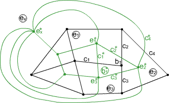
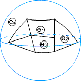
Dual complexes: here $X$ is in black, $X^*$ in green. $X$ is drawn as a planar graph with applications to circuits in mind, but the total space is a sphere, with an additional hexagonal cell $e_x$.
